Drive Train Analysis
Requirements and Considerations
In order to properly size the motors, gearboxes (if necessary), and wheels, expected operating conditions were first established. The table below describes a few parameters and their expected values.
| Parameter |
Value |
|---|---|
| Max supply voltage |
7.2 V |
| Number of driven wheels |
2 |
| Max robot mass |
5.6 kg (12.24 lbs) |
| Min linear speed |
0.15 m/s (0.5 ft/s) |
In addition, the driver circuit will also effect the feasibility of chosen motors. For simplicity, the L293 driver board was chosen, as it is already available, and requires very little additional components to use. The important characteristics of the driver circuit are shown in the table below.
| Parameter |
Value |
|---|---|
| Max supply voltage |
5 to 36 V |
| Max output drop |
3.6 V |
| Max output current |
1 A |
Dynamic motor performance
To determine how the motor would perform under the desired parameters, it is necessary to take a force balance and torque balance to determine the linear and angular velocities and accelerations.

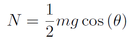
From the force balance in the y-direction, it is possible to determine the normal force supporting the wheel. Note that since two wheels are driven and two wheels are passive (casters), the normal force that the motor needs to handle is half of the total robot mass.
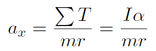
The force balance in the x-direction, it is possible to determine the linear acceleration, which will be in terms of the torques exerted about the driven wheels. This can be rewritten in terms of the angular acceleration of the wheels, from the torque balance.
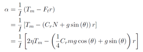
Finally, the torque-balance yields the angular acceleration of the wheels. The torque that resists the motor consists of a rolling resistance and the effects of gravity, if the robot is on an incline.
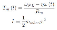
In addition to the previous expressions, the relationship between motor torque and angular speed is also required to determine how the motor performs after the initial acceleration from stall. The wheel moment of inertia is also shown below.
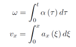
Taking the integral of the expressions for angular and linear accelerations will yield the angular and linear speeds, respectively. These expressions will be used to determine how fast the robot will reach its steady-state speed, and the top speed of the robot.
Results for chosen parts
Using the previous analysis and MATLAB, a motor/gearbox/wheel system was analyzed for feasibility. Note that the worst case parameters were used; specifically, the motor voltage was reduced by the voltage drop specified in the table for the driver specifications. The table below shows the parameters for the entire system. Some of the parameters had to be estimated as there was no tabulated value.
| Parameter |
Value |
|---|---|
| Motor voltage |
6 V |
| Stall current |
0.35 A |
| Stall torque |
8800 gf-cm |
| No-load speed |
133 rpm |
| Wheel radius |
50.8 mm (2 in) |
| Wheel mass |
200 g |
| Expected efficiency |
75% |
The figure below shows that the robot will have a top speed of approximately 1.25 m/s (4.1 ft/s). As a result, the expected time to traverse 8 ft is about 2 seconds. Considering that the motor specifications were heavily estimated for this motor (as Jameco did not provide a manufacturer datasheet), these results should be taken with a grain of salt. A conservative estimate puts the time to travel the length of the field at around 5 seconds.
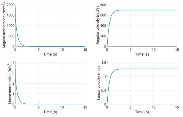
Simulation results for chosen motor/gearbox/wheel system.
